

710613 BUS HUB
Date:
Wednesday, 20 November 2019
To:
Sam Parkinson
From:
Swastika Mishra
SUBJECT:
JOHNSONVILLE BUS STAND OPTION ASSESSMENT
Introduction
GWRC has requested Calibre to investigate two options to incorporate a proposed bus parking area (Bus Stand) into
Johnsonville Bus Stop C, which is currently under construction on Moorefield Road.
The two options presented are:
1. Maintain the existing kerb line on the western side of Moorefield Road, and install the Bus Stand within the existing
carriageway where the two exit lanes from the Broderick Road traffic signals currently merge; and
2. Modify the existing kerb line on the western side of Moorefield Road to allow the Bus Stand encroachment into the
existing traffic lanes to be minimised.
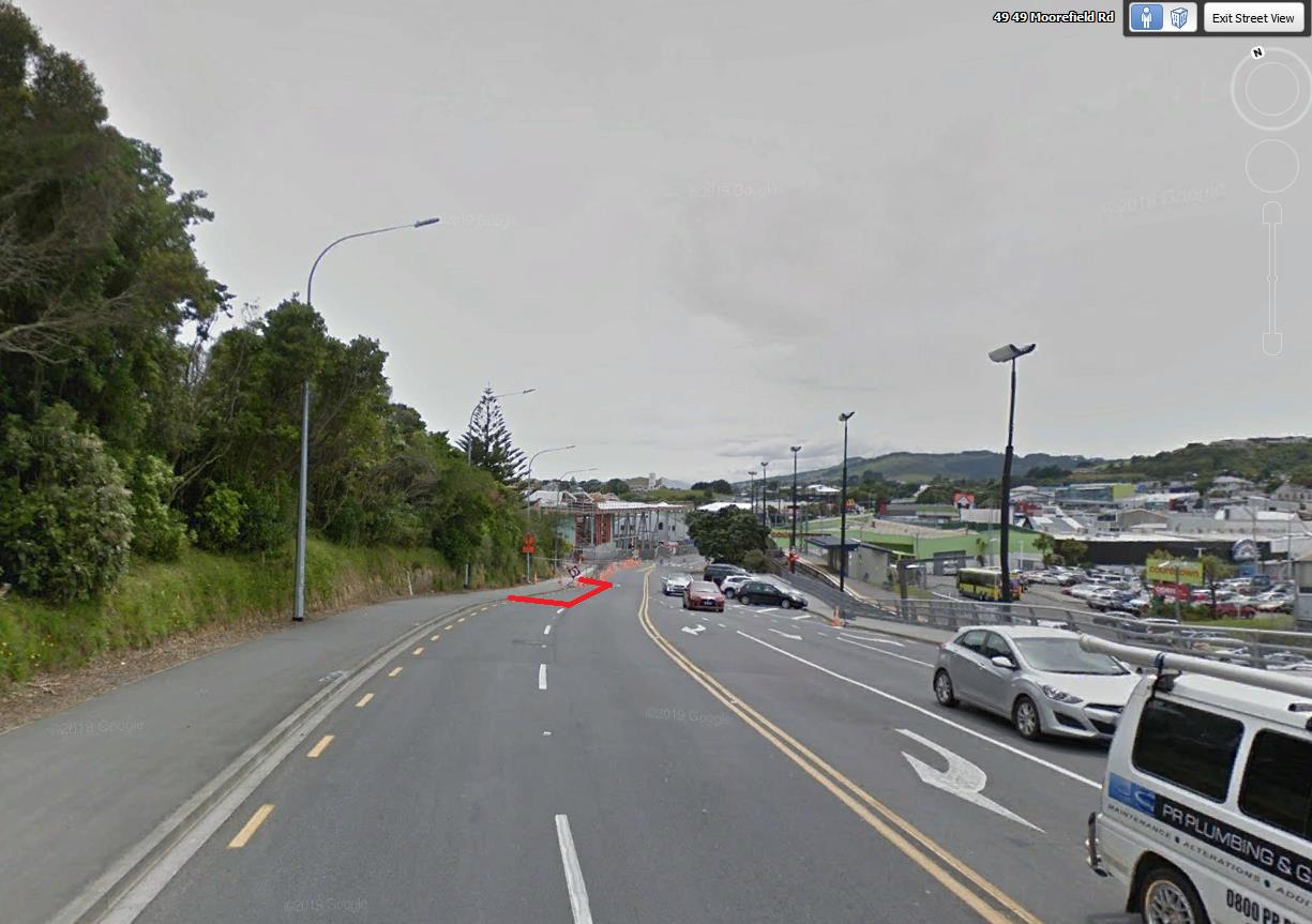
The proposed Bus Stand location is located immediately north of the existing Broderick Road/ Moorefield Road traffic signals
(refer Figure 1). The two northbound exit lanes merge to one lane approximately 60m north of the intersection. The proposed
Bus Stand would be within the existing two lane to one merge area.
This report summarises a consideration of Option 1, primarily to determine whether this option (which leaves the existing kerb
lines intact) could be safely implemented.
Figure 1 Streetview of existing road layout - proposed Bus Stand shown in red
Our Ref: Feasibility Design
Page
1 of
4


710613 BUS HUB
CONTINUED
Design References
1) Austroads Part 3: Geometric Design
2) MOTSAM Section 2: Pavement Markings
3) MOTSAM Section 3: Intersection Pavement Markings
4) NZTA Guidelines for Public Transport Infrastructure and facilities
Assumptions
1) The designs have been assessed using available LINZ aerial imagery data.
2) WCC Kerbs downloaded from
https://data-wcc.opendata.arcgis.com/datasets/wcc-kerb - (assumed they are edge of
seal from below statement)
3) Posted speed limit is 50 km/h
Proposed Option 1 Layout
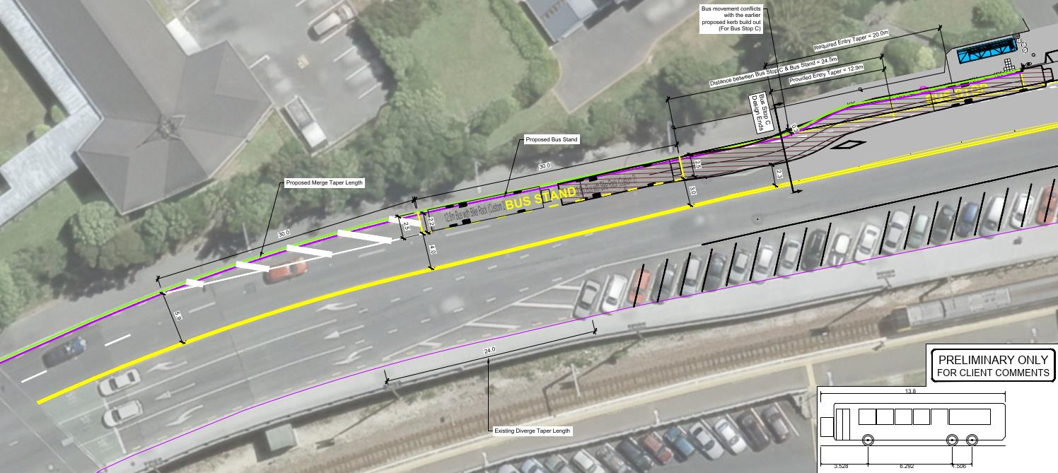
The Bus Stand layout proposed under Option 1 is shown below (Figure 2)
Figure 2 Option 1: Proposed Bus Stand layout
Key features of this layout include:
Introducing a new merge taper (and associated cross hatching) which reduce the merge length for vehicles exiting the
adjacent traffic signals.
Retaining the existing kerb locations, including the newly constructed kerbs for Bus Stop C.
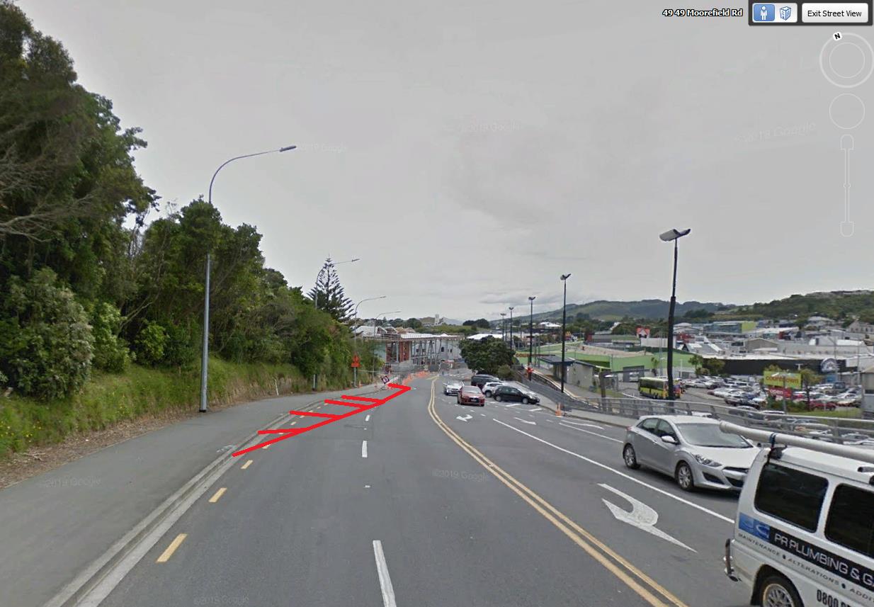
An impression of what the new merge taper might look like to approaching motorists is shown in Figure 3.
Page
2 of
4


710613 BUS HUB
CONTINUED
Figure 3 Impression of proposed new merge taper (Option 1) for approaching motorists
Discussion
Using the design criteria from the Austroads Guide to Road Design Part 3: Geometric Design, and an assumed 85th percentile
speed of 40 km/h, the desirable merge taper length is approximately 46m. However, it is not possible to incorporate such a long
merge taper due to the proximity of the traffic signal exit lanes. I.e. vehicles would be required to merge immediately after exiting
the intersection which would likely affect the intersection capacity).
In urban situations it is relatively common to introduce much shorter merge tapers due to physical constraints, which require
motorists to merge at a slower speed. A nearby example is the southbound exit lanes from the Johnsonville Road roundabout
where a merge distance of approximately 35m is provided.
It is therefore considered appropriate in such a built up urban environment to introduce a 30m merge taper at this location. This
shorter taper may increase the likelihood of vehicle conflict, however the provision of the cross-hatched shoulder will mitigate
this risk to some extent by providing an area for motorists to avoid conflict.
There may be a temptation for bus drivers to park their vehicles within the cross hatched area in the event that the Bus Stand is
occupied upon arrival. This practice would need to be actively discouraged (perhaps by the introduction of broken yellow lines or
hit stix) as buses parked so close to the intersection could affect signal capacity and reduce motorist safety in the merge area.
A further consideration is that buses parked in the Bus Stand adjacent to the kerb would need to pull out from the kerb and then
turn into Bus Stop C. In this situation the tail of the bus is likely to encroach into the single remaining traffic lane, with a possibly
of conflict with passing vehicles. This risk could be mitigated by ensuring that bus drivers check that there are no vehicles
approaching from their rear before pulling out, as required under existing land transport rules.
A road layout has yet to be developed for Option 2, however this would likely involve narrowing the existing footpath to allow the
Bus Stand to be ‘indented’ – reducing encroachment on the live traffic lanes. This option is unlikely to present a significant
benefit in terms of merge taper length, as it appears unlikely that the Bus Stand would be able to be fully indented without
Page
3 of
4


710613 BUS HUB
CONTINUED
reducing the footpath to a substandard width. The indentation would also not resolve the issue with the bus tail encroaching into
the live lane when turning into the Bus Stop.
Conclusion:
It would be possible to introduce a Bus Stand parking area within the existing carriageway on Moorefield Road as shown, by
introducing a 30m merge taper on the exit from the traffic signals.
The merge taper will be substandard compared to technical guidelines, and will require vehicles to merge at a lower speed
when exiting the traffic signals. Merge tapers of such lengths are not uncommon in urban environments, but do come with an
increased risk of vehicle conflict.
Buses drivers parked in the Bus Stand would be required to check their mirrors and make sure no vehicles are approaching
before pulling out form the kerb and turning into the Bus Stop to prevent conflict with the tail of the bus and passing vehicles.
Active measures may need to be taken to prevent buses from parking in the cross hatched shoulder area, as this might affect
the capacity of the adjacent intersection and reduce motorist safety.
A detailed Design exercise would need to be undertaken to finalise the geometric details of the proposed option.
Attachment:
1) Calibre Design Layout Plan:
710613-B-C30-John
sonville Bus Stand_Rev0.pdf
Page
4 of
4


