Trimester 2
Test 2 – 2021
ENGR 142
Engineering Physics
Time Allowed:
24 hours
OPEN BOOK
Permitted materials: Calculator, notes, textbook, online tools (e.g., matrix solver).
Instructions:
Answer
All questions.
Total marks: 50
ENGR 142
Page
1 of
6
Part 1: DC electricity
Problem 1 (6 marks)
(a) A 50 cm copper wire has a radius of 0.2 cm. The resistivity of copper is 1.7×10⁻⁸ Ω·m
at 20 ◦C.
i) Determine the resistance of the wire at 20 ◦C.
(1 mark)
ii) Determine the resistance of the same copper wire that is 1 m long (i.e., twice as
long), also at at 20 ◦C.
(1 mark)
(b) Current flows in a wire. The quantity of charge (in coulombs) that has passed through
a cross-sectional area of the wire varies with time according to the equation: Q(t) =
4t2 + 2t + 1.
i) Determine the equation for current as a function of time, I(t).
(1 mark)
ii) Calculate the instantaneous current at t = 2 s.
(1 mark)
(c) Two parallel plate conductors have a potential difference of 12 V between them and a
net charge of +9.0 pC and -9.0 pC (1 pC = 1.0×10⁻¹² C).
i) Calculate the capacitance of the system.
(1 mark)
ii) Calculate the area of each plate, if the distance between the plates is 5 cm.
(1 mark)
ENGR 142
Page
2 of
6


 Problem 2 (8 marks)
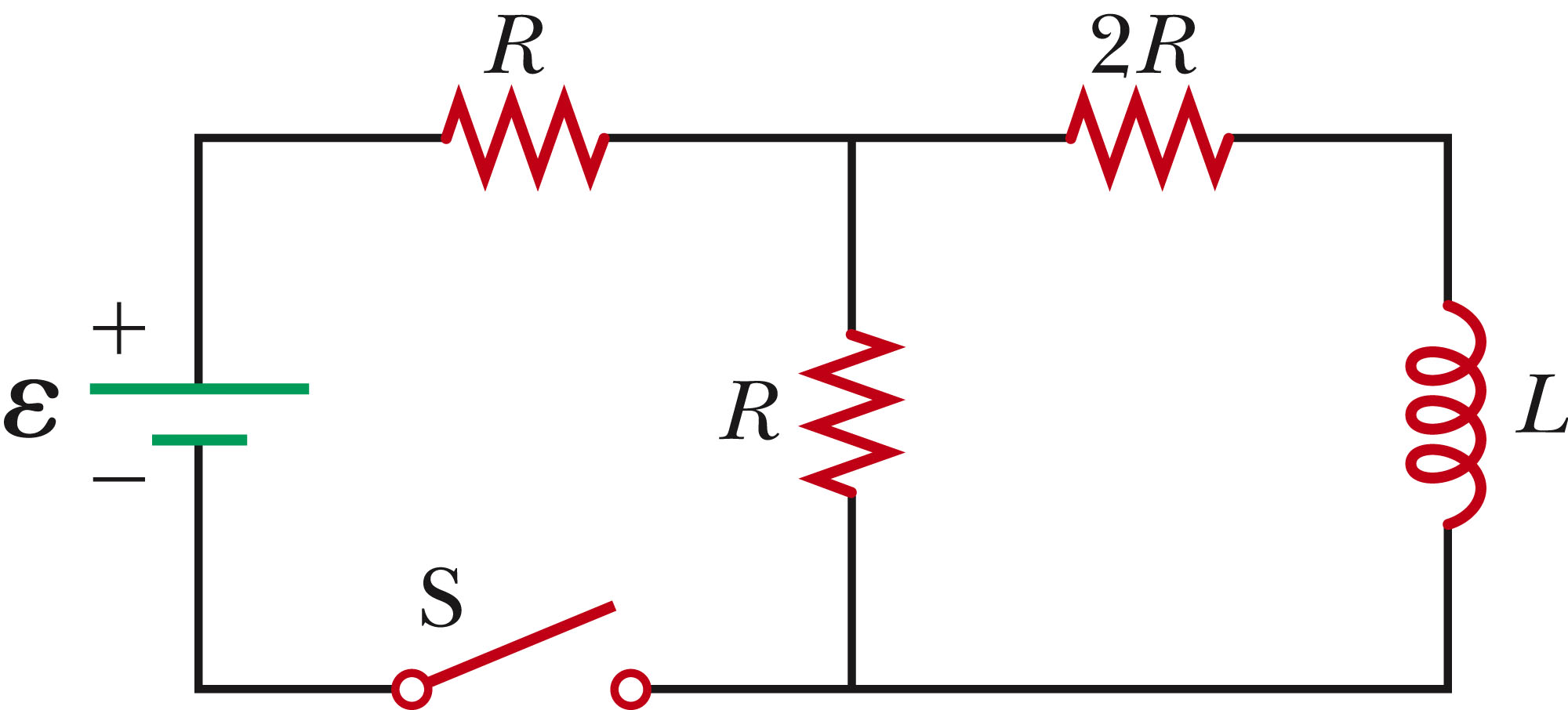
Consider the circuit shown in the figure below. The circuit element values are: R1 = 2 Ω,
R2 = 6 Ω, R3 = 12 Ω, L = 6 mH, and
ε = 12 V.
After a long time with the switch open (no current flowing), the switch is closed at t = 0 s.
(a) Determine the time constant for circuit,
τ.
(2 marks)
(b) Determine the total current as a function of time, Itot(t).
(2 marks)
(c) Calculate the total current in the circuit one time constant after the switch is closed.
(2 marks)
(d) Determine the maximum current for this circuit.
(2 marks)
ENGR 142
Page
3 of
6
 Problem 3 (8 marks)
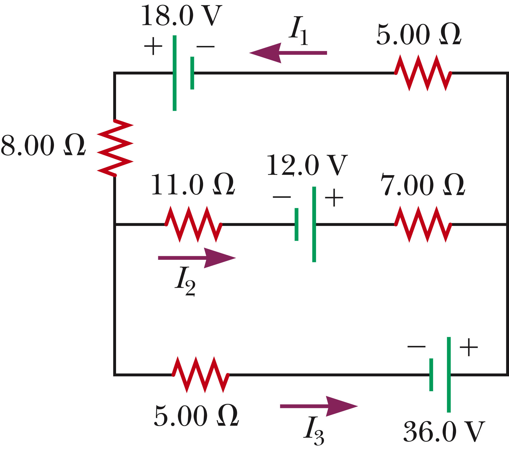
Consider the circuit shown in the figure below.
(a) Either in the figure above or a copied drawing of the circuit, clearly draw and label
i) the Kirchoff’s junction you will use. Label this junction J1.
(1 mark)
ii) the Kirchoff’s loops you will use . Label these loops L1 and L2.
(1 mark)
(b) Write out the three equations resulting from Kirchoff’s laws.
(3 marks)
(c) Determine the values of I1, I2 and I3.
Note: If you use a mathematical, calculator
or online tool to solve for the currents, clearly list which tool you used (e.g., ‘I used
Matlab’s matrix equation solver to solve for the currents.’) Also, clearly write out
what it was that you plugged into the tool (e.g., in the previous example, write out the
matrices that you entered into Matlab.)
(3 marks)
ENGR 142
Page
4 of
6
Problem 4 (14 marks)
Consider the problem of first order filter design.
(a) Design a first order filter that attenuates all frequencies below 10,000 rad/s by 3 dB or
more relative to the passband. One of your components should be a 100 Ω resistor, but
you can pair it with either a capacitor or an inductor. Draw the resulting diagram clearly
labeling the output voltage and the components used.
(5 marks)
(b) For the above filter, how much attenuation will frequencies at 100 rad/s experience?
Explain your reasoning.
(3 marks)
(c) What frequencies will be attenuated by 30 dB or more?
(6 marks)
Problem 5 (14 marks)
Consider a series RC circuit consisting of R = 10kΩ and C = 100 nF. The voltage source is
˜v = 106 90◦ (
rms) operating at a frequency of 50 Hz.
(a) Find the real, reactive and apparent powers.
(5 marks)
(b) What is the current i(t).
(1 mark)
(c) The frequency is now increased to 100 Hz. What inductor needs to be placed
in par-
allel with the capacitor to achieve the same power factor as for the original circuit
operating at 50 Hz? You must explain your reasoning.
(8 marks)
ENGR 142
Page
5 of
6
* * * * * * * * * * * * * * *
ENGR 142
Page
6 of
6