ENGR142
Test 2
3 November 2023
Name: ………………………………………………………………………
Student Number:……………………………………………………….
Instructions – please read
Time = 120 minutes
Total = 80 marks
Attempt all questions. All questions are worth equal marks and you should spend
approximately 15 minutes on each question.
You can bring one A4 sized sheet with your own notes on both sides with you into the
test.
Write and/or sketch your answers in the open spaces provided on this test sheet. Show the
details of your workings where appropriate – do not just show the final answer. A blank
sheet is provide at the back if you should need more space. Ensure that all answer sheets
are handed in.
The values of some selected constants are provided on page 2 and the test starts on page 3.
Question
Marks
Obtained
1
10
2
10
3
10
4
10
5
10
6
10
7
10
8
10
Maximum
80
marks
1
Selected physical constants
Electron charge
q
1.9 x 10⁻¹⁹ C
Atomic mass unit
amu
1.66 x 10⁻²⁷ kg
Avogadro’s number
NA
6.02 x 10²³ mol-1
Boltzmann constant
k or kB
1.38 x 10⁻²³ J.K-1 = 8.62 x 10⁻⁵ eV.K-1
Electron charge
e
1.6 x 10⁻¹⁹ C
Permeability of vacuum
μo
4π x 10-7 H.m-1
Permittivity of vacuum
εo
8.85 x 10⁻¹² F.m-1
Plank’s constant
h
6.626 x 10⁻³⁴ J.s = 4.136 x 10⁻¹⁵ eV.s
Speed of light
c
2.99 x 10⁸ m.s-1
2
Question 1.
[10]
Select the answer that best matches each statement or question by placing an X in the
appropriate ⃝
:
(a) The electrical resistance in a conductor is:
⃝ Directly proportional to the conductivity of the material
⃝ Directly proportional to the length of the conductor
⃝ Directly proportional to the cross-sectional area of the conductor
⃝ Constant with temperature
(b) In the circuit below the capacitor is initially discharged before the switch closes.
I1
R1 =
R3=10
V=10V
R2=10
C=10 µF
The current I1 at time t=0 (immediately after the switch closes) is:
⃝ Infinitely high
⃝ 0 A
⃝ 1 A
⃝ 0.67 A
3
(c) Consider the circuit below, where R1 < R2 < R3 < R4 < R5:
R1
R4
R5
R2
R3
V
The total resistance of the circuit, RT, will be:
⃝ RT < R1
⃝ RT > R5
⃝ R2 < RT < R3
⃝ Impossible to say without actual resistor values.
(d) For the circuit below, what would be the approximate time between the closure of the
switch and when the capacitor can be considered fully charged.
R=1 k
V=5V
C=10 µF
⃝ 10 ms
⃝ 30 ms
⃝ 50 ms
⃝ 100 ms
4
 (e)
(e) An AC voltmeter measures across the terminals of an AC generator that outputs a
frequency of 45 Hz and measures a voltage of 7.07 V. The expression that describes the
output of the generator is:
⃝ v(t) = 7.07sin(45t)
⃝ v(t) = 10sin(45t)
⃝ v(t) = 7.07sin(283t)
⃝ v(t) = 10sin(283t)
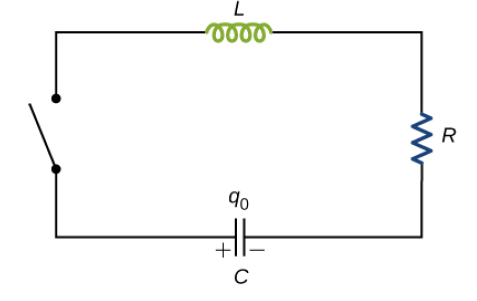
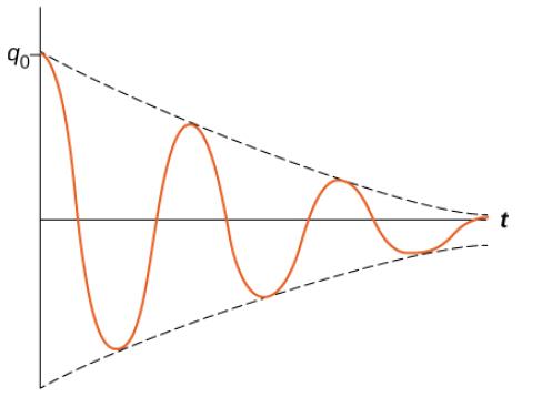
(f) In the RCL circuit below the capacitor is charged before the switch is closed. The charge
over the capacitor is then observed with time and the plot shown below is obtained.
From this behaviour of charge over the capacitor, what would be the approximate
relationship between R, L and C
⃝ R = 0 with no influence from L and C
⃝ R << 2√(𝐿/𝐶)
⃝ R = 2√(𝐿/𝐶)
⃝ R >> 2√(𝐿/𝐶)
5
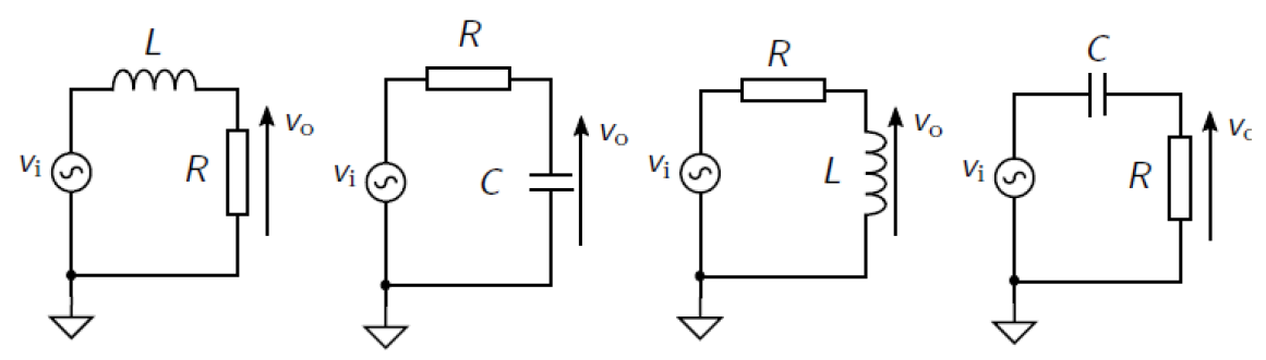 (g)
(g) The circuits for four first order filters are shown below, with vo indicating in each
instance where the output signal is measured.
(a)
(b)
(c)
(d)
Which of the above circuits act as a high pass filter ?
⃝ (a) and (b)
⃝ (a) and (c)
⃝ (b) and (c)
⃝ (c) and (d)
(h) Consider the capacitor in the circuit below.
+V
R1
Input
Output
Amplifier
Amplifier
Stage 1
Stage 2
C
R2
The main function of this capacitor is:
⃝ To block AC and pass only DC to the next amplifier stage
⃝ To block DC and pass only AC to the next amplifier stage
⃝ To delay any signal between the two amplifier stages by one time constant
⃝ To totally electrically disconnect the two circuits.
6
Question 2:
[10]
(a) Consider a length of electrically conducting wire with a cross sectional area A. The
conductor contains a density of charge carriers n (carriers/unit volume) and these charge
carriers move with an average drift velocity vD when an electric field is applied.
Use the definition of electric current to derive an equation relating the electric current to
the density of charge carriers, the cross-sectional area and the average drift velocity.
(5)
7
(b) A cylindrical electrical conducting wire has a length of 15 cm and a diameter of
2 mm. It
is given that the conducting material has a resistivity of 8 x 10⁻⁸ Ω.m.
(i) Calculate the resistance of this wire.
(2)
(ii) Calculate the amount of charge that will flow through the wire in 10 seconds if a voltage
of 1 V is applied over the ends of the wire.
(3)
8
Question 3
[10]
(a) (i) Calculate the capacitance of two rectangular conducting plates, each with dimensions
10 x 10 cm and with a separation distance of 5 mm between the plates.
(2)
(ii) A piece a 5 mm thick Teflon with a dielectric constant of 2.1 is inserted between the
plates in (i). Calculate the new value of the capacitance.
(1)
(iii) Explain with the aid of a sketch why the observed value of the capacitance will change
when a dielectric is inserted between the plates.
(2)
9
(b) (i) Calculate the inductance of a helical air-filled coil with a length of 20 cm, a cross
sectional area of 30 mm2 and consisting of 400 turns of wire.
(3)
(ii) What would be the energy stored in this coil if a current of 5 A is passing through it ? (2)
10
Question 4
[10]
I1
For the circuit on right calculate:
(i) The total resistance
(2)
R1 = 12k
(ii) The currents I1, I2 and I3 (3)
A
I3
(iii) The voltage at point A
(2)
V=24V
R1 = 6.2k
(iv) When constructing the circuit, a resistor with
I2
value 100 Ω is accidently used for R4. Explain
R4 = 100k
qualitatively what will be the result on the circuit
R1 = 5.8k
performance, particularly with reference to the
previously calculated values of VA and I3. (3)
11
12
Question 5
[10]
(a) (i) State Kirchoff’s two rules in words.
(2)
(ii) Use these rules to write a set of equations for the circuit below that can be used to
calculate the magnitudes and directions of the resultant currents.
(3)
V1
R1
-
+
R2
V2
I1
R
R
3
I2
-
+
4
I3
V3
+
-
R5
13
(b) In the circuit below, the signal generator outputs a square wave Vs of 0 to 1 V with a
frequency of 1 kHz.
R=10
Vs = 1 V
L=10 mH
fs = 1 kHz
(i) Sketch a graph of the input waveform Vs with time for one complete cycle.
(1)
(ii) What is the time constant of the circuit?
(1)
(iii) Sketch a graph of the current in the circuit with time for one complete input cycle. (2)
(iv) Calculate the maximum value of the current in the circuit.
(1)
14
Question 6
[10]
Calculate the impedance at 5 kHz for each of the circuits below. Show your result in both
rectangular and polar form and plot the resultant impedance value on the complex plane.
(i)
L = 10 mH
R = 5 k
C = 20 µF
(5)
(ii)
C = 20 µF
R = 5 k
L = 10 mH
(5)
15
Question 7
In the circuit below, calculate the output voltage vo if C = 20µF, R1 = 5kΩ, L = 10 mH, R2 =
5kΩ and the input voltage v(t) = 20sin(250t).
(10)
C = 20 µF
R1 = 5 k
R
vo
2 = 5 k
v(t)=20sin250t
L = 10 mH
16
Question 8
[10]
(a) Design a first order high pass filter that has a corner frequency of 10 kHz. Base your
design on a resistor of 1 kΩ and determine the appropriate value(s) for the other
component(s). Sketch you circuit and clearly show the input and output of your filter.
(5)
17
(b) The circuit below shows a Schmitt trigger inverter connected to an external resistor and
capacitor.
R
5 V
Vi
Vo
C
(i) What do we call this type of circuit and what would be a typical application?
(2)
(ii) Sketch both the expected voltage at the input (Vi) and the voltage at the output (Vo) with
time. Clearly show the timing relationship between these two signals.
(3)
*****End of Test*****
18
19
20